06/8/20

Chase Bliss Thermae: The missing knob


This time what I wanted to do is create a Time knob for my Thermae pedal, the most wanted control missing in the Thermae due to being so small.

My solution uses Midi clock messages to set the wanted time.

The tricky part is the envelope trigger. Thermae doesn’t accept any midi command to restart the sequence, so the only way I found to sync the interval sequences my music was to engage the pedal just when audio is detected. This is especially useful to get more controlled results when recording for example.

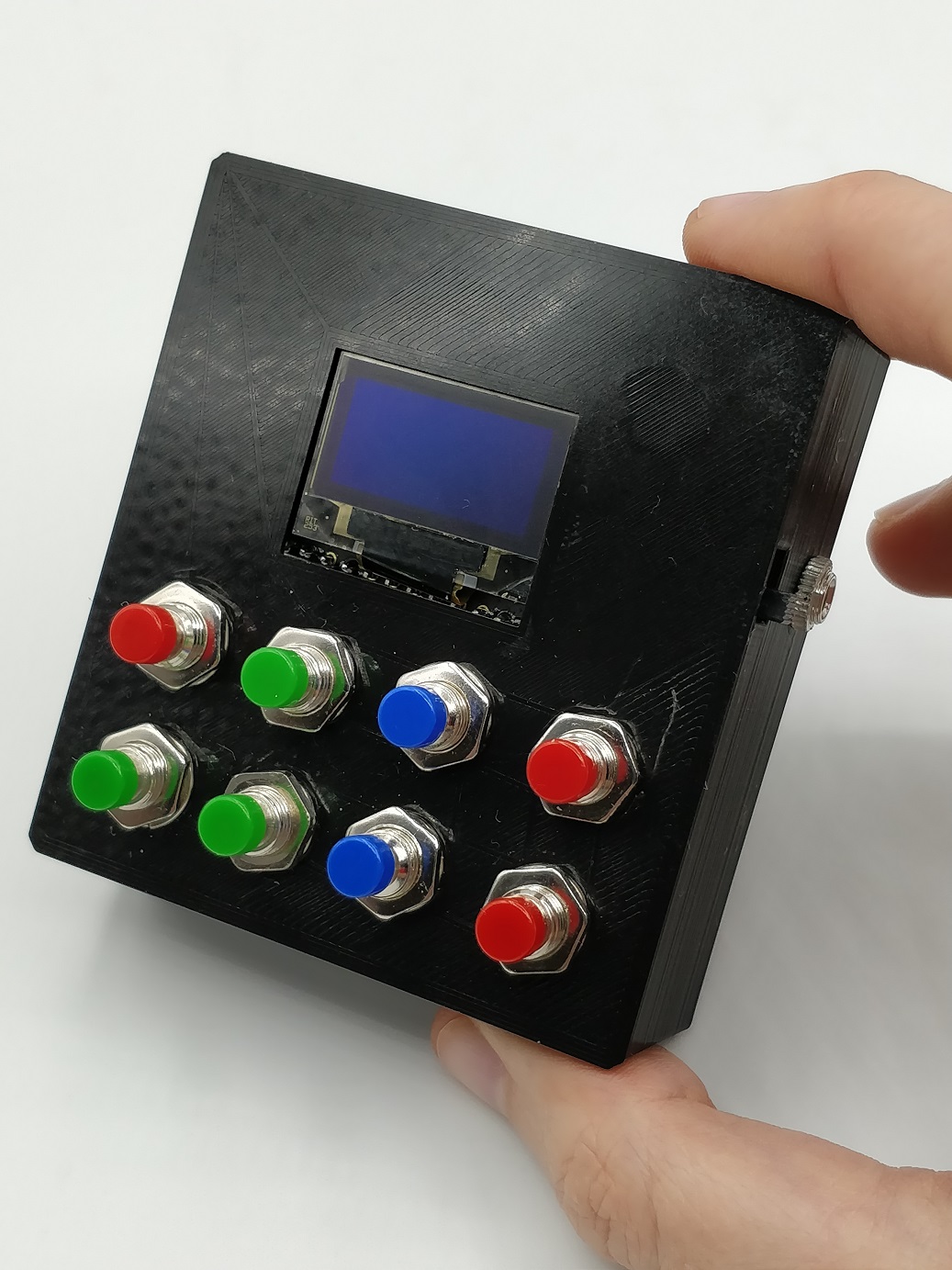
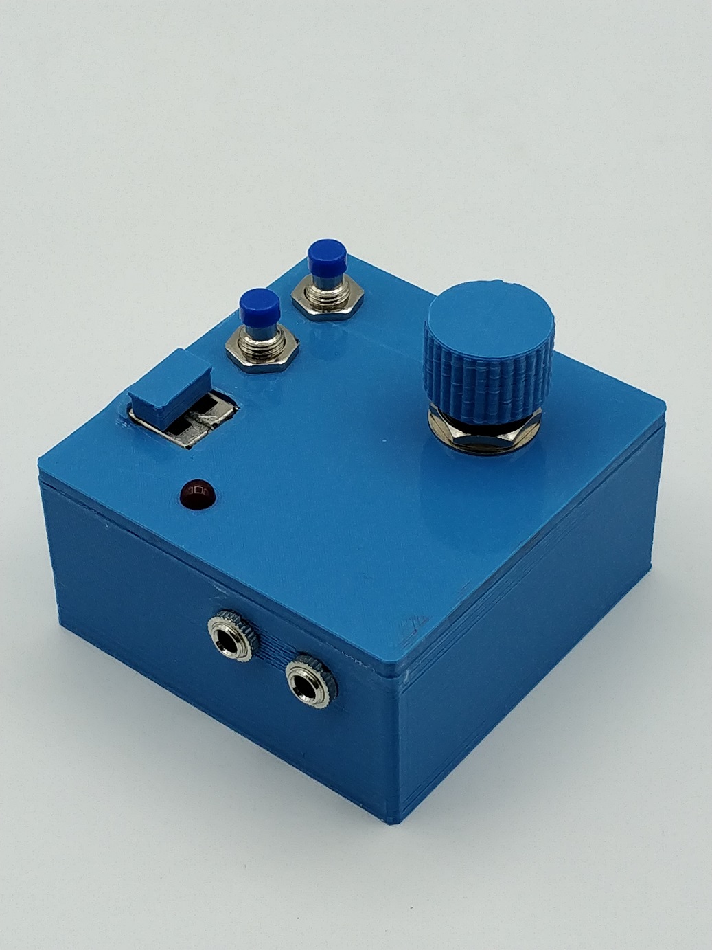
This little box adds:

  • Time select knob, from a few ms to 1s (higher times are more useful with the tap tempo).
  • Two modes (selectable by the switches):
    • Time mode: Select the time with the knob
    • Trigger mode: Knob doesn’t work in this mode. The two buttons add or reduce input audio sensibility.
  • LED to check input trigger in trigger mode.
  • 3.5mm TRS input for incoming audio (trigger)
  • 3.5mm TRS output to connect to Thermae.
  • Toggle slow mode (only in time mode): pressing the two buttons

Midi CC messages:

  • Delay mode:
    • Send the value 248 (decimal) to channel midi #2 (Thermae default). Desired time / 24 is how often you have to send this data to the pedal so it can change the tempo.
  • Disable slow mode: CC #25 = 0
  • Enable slow mode: CC #25 = 127
  • Trigger mode (I ignore midi clock in trigger mode):
    • Disable midi clock: CC #51 = 0
    • Enable midi clock (delay mode): CC #51 = 127
    • Engage pedal: CC #102 = 127

When in trigger mode, I always suppose the pedal is in bypass (not engaged), so if audio is detected the engage pedal message is sent from the box to the pedal via midi.

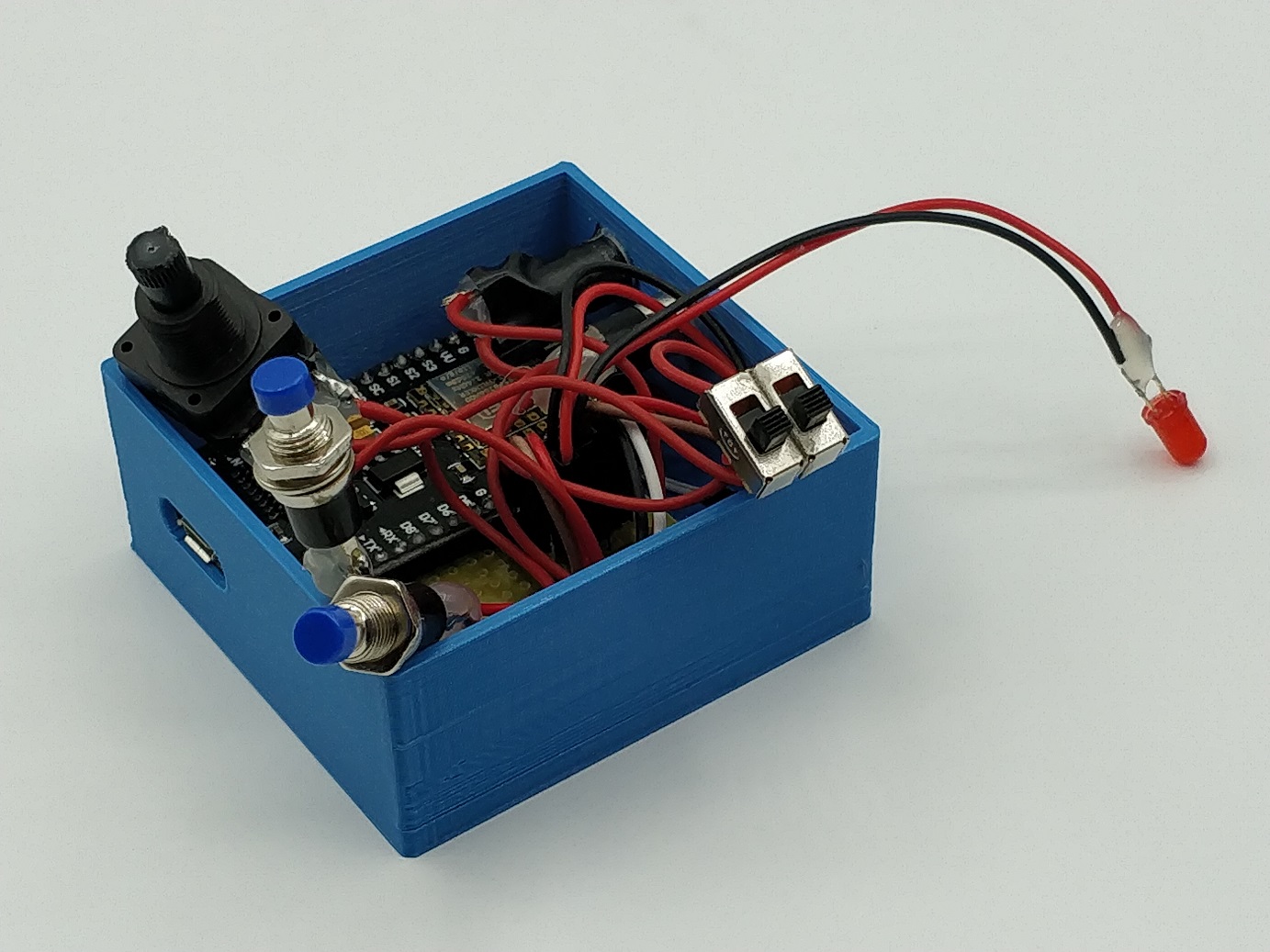
The commuter is used to physically connect the input audio to the arduino internal analog/digital converter, which also will disconnect the knob in my case (easy fix is use a board with more ADC). Depending on the value read by this converter, we’ll trigger the engage the pedal or not. The LED allows to see easily if the signal was strong enough, but depending on the input instrument (in my case line-level keyboard) the threshold can be trickier to find. I have not tried it with guitars.

Hardware notes:

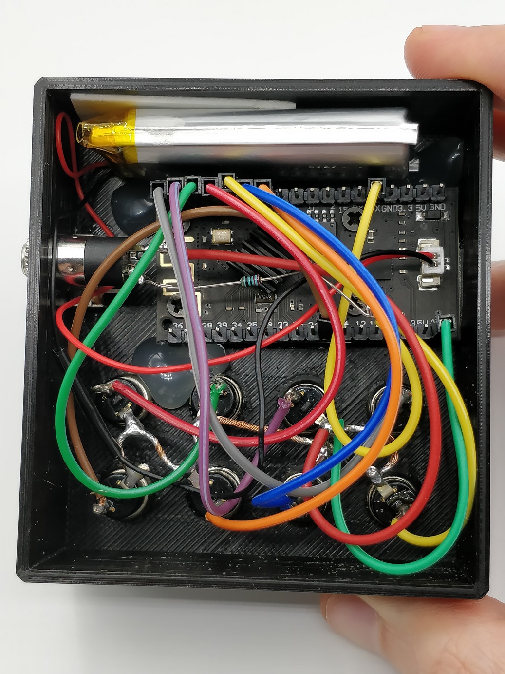
  • It is necessary an Arduino board with serial pins like UNO or in my case the nodeMCU, but there are many boards that would be ok: https://es.aliexpress.com/item/32824839148.html?spm=a2g0s.9042311.0.0.274263c0kSWu0n
  • Any push buttons or commuters will work, but need pull-up resistors or at least use the INTERNAL_PULLUP flag configured in the input pins of the program.
  • 3.5mm midi output jack is connected to the TX pin of the microcontroller via a 220ohm resistor.

Midi Wiring:

Thermae has a TRS connection. The pedal sleeve pin will go to our 3.5mm sleeve, ring with ring and tip is not connected (it is used for additional footswitch). Remember to use the 220ohm resistor from the ring to the microcontroller TX (transmit) pin.

Example:


I am working on improving some of the current drawbacks like having to choose either delay / trigger, and also the threshold select is not the most comfortable to use, but that will imply changing some of the current components.


05/19/20

Expanding Chase Bliss Blooper pedal possibilities


I recently got my Chase Bliss Blooper pedal and even before receiving it I started building a standalone device that would allow me to trigger momentary effects and anything else that would be nice to have, all through the midi jack, because I prefer to not use the PC most of the times and also this way would allow me to create any specific sequence of commands, like custom intervals or glide option similar to a Thermae.
Just imagine adding 3 more pots to this box: time, interval 1, interval 2 for example, to add rhythmic pitch-shifting intervals.

Disclaimer: Build this at your own risk, it may have worked for me but maybe I haven’t connected it the most secure way so keep this in mind.

The arduino code can also be useful to see the necessary midi sequences for the functions I already mentioned to apply them in other controllers.

So my first program adds:

  • Half speed record: Records a loop of double of the recorded time. Then, it automatically applies half speed in aditive mode so it fits perfectly in time once effect is applied.
  • Momentary octave down (with or without glide)
  • Momentary octave up (with or without glide)
  • Momentary Max stability – Specific delay time from 0ms to 32s

Midi CC messages of my new custom functions:

  • Custom delay:
    1. Clear loop: CC 7 = 1
    2. Rec: CC 1 = 1
    3. Wait the wanted time
    4. Play: CC 2 = 1
    5. Overdub: CC 3 = 1
  • Octave up (momentary effect, no glide*):
    • Press:
      1. Set Octave +1: CC 19 = 109 (or 14 to reverse)
      2. Enable Mod B: CC 31 = 1
    • Release:
      1. Disable Mod B: CC 31 = 1
  • Octave down (momentary effect, no glide*):
    • Press:
      1. Set octave -1: CC 19 = 79 (or 44 to reverse)
      2. Enable Mod B: CC 31 = 1
    • Release:
      1. Disable Mod B: CC 31 = 1
  • Max stability (momentary effect):
    • Press: CC 18 = 127 (max stability)
    • Release: CC 18 = 0 (no stability)
  • Double REC time:
    • 1st press (start recording):
      1. Rec: CC 1 = 1
    • 2nd press (stop recording):
      1. Wait the same amount of time that took from 1st press to 2nd.
      2. Stop: CC 4 = 1
      3. Set half speed: CC 19 = 79
      4. Enable Mod B*: CC 31 = 1
      5. Overdub: CC 3 = 1
      6. Wait TWICE the time in step 1.
      7. Stop: CC 4 = 1
      8. Disable Mod B: CC 31 = 1
      9. Play: CC 2 = 1

I suppose the modifier switch of mod A/B are already set in my case but it’s easy to add if necessary. Also I suppose we’re in additive mode to apply the half-speed effect.

The glide option is more tricky to explain, it’s better to check the code. I use mod A smooth speed to make the glide effect and once reached the glide time then disable mod A and enable mod B stepped speed to get a perfect octave.

Materials needed to create a the controller:

  • Arduino with serial pins like Arduino UNO or in my case this one: https://es.aliexpress.com/item/32824839148.html?spm=a2g0s.9042311.0.0.274263c0kSWu0n
    The screen is not necessary if you don’t mind not seeing the exact delay time or want to use other less specific options.
  • LiPo battery: I used this because the Arduino board already has a battery connector and the same board also works as a charger, but it can also be powered by microUSB with no problems.
  • Push buttons or other input components for the interface. I did the most simple interface with push buttons but it would be easily expanded with some pots using ADC converters like the MCP3008 via SPI protocol. I don’t even use pull-up resistors because arduino already allows me to use the INTERNAL_PULLUP in the input pins.
  • 3.5mm output jack, connected to the TX pin of the microcontroller via a 220ohm resistor

Midi Wiring:

Blooper has a TRS connection. For this controller, the Blooper sleeve pin will go to our 3.5mm sleeve, ring with ring and tip is not connected (it is used for additional footswitch). Remember to use the 220ohm resistor from the ring to the microcontroller TX pin.

Arduino code: https://elgaratge.com/download/blooper-expander/

Example:

Feel free to contact me on reddit / youtube if anything is not clear, if you want to share your version or if you have an idea for a useful function even you don’t know how to implement it.

https://youtube.com/efimer

https://www.reddit.com/r/blooper/comments/gma7mf/i_built_a_standalone_device_to_add_more_functions/


09/21/14

Low cost laser barrier Photography

_MG_9916-2

After trying to capture an exploding water balloon with a very rudimentary method (see here), I dedided to try again but using a low cost laser barrier and a LDR (Light-dependent Resistor) to get more accurate results.

Materials:

  • 1 Laser diode (5v, a pack of 10 is very cheap on eBay).
  • 5v Power supply (or 4xAA batteries) for powering the laser.
  • 1 small LDR (Light-dependant Resistor)
  • 100K variable resistor
  • N3 camera connector (Canon 5D) or minijack depending on camera model.
  • Bag of water balloons
  • Also a flash is necessary to freeze the motion, and also using it at the minimum power possible.

Circuit:
 
Knowing that to shoot the camera with an external cable we need to short-circuit two wires (Shutter and Ground), I put a 100K variable resistor between the two wires and saw that the camera shoot when I set the resistance lower than 25K.
Once we know that resistance, we know that if the sum of the variable resistor + LDR is < 25K, the camera will shoot.
To build the circuit I just put the LDR and the variable resistor in serial and then connected them to the shutter and ground cables of the camera. The variable resistor serves to callibrate the initial status and set the camera to a point that almost shoots. Then, when we point the laser to the LDR, its resistance lowers and the overall resistance between the Shutter and Ground cables will be < 25k, so the camera will shoot. In normal conditions, when the water balloon is in front of the LDR, the camera won’t shoot because the LDR resistance is too high to trigger the camera. When the water balloon explodes, the laser beam will illuminate the LDR.

Camera and flash settings:

  •  Shutter: 1/125 (if there’s ambient light it should be faster).
  •  Lens focus set to manual.
  •  ISO 400
  • Apperture: f/8-f/12 to get enough DOF.
  • Flash power set to 1/64 and zoom at 105, about 60cm from the water balloon (on the left). Also, the flash is triggered from a remote emitter in the camera.

Once all is prepared, we just have to tie a water ballon to the rope so that it is placed between the laser and the LDR, and when we make the balloon explode with a needle the camera will automatically shoot.

Original idea:

20140921_191817

Setup and circuit:

20140921_154954 20140921_155034 20140921_155136 20140921_155223 20140921_174249 20140921_180640


Results:

_MG_9912_MG_9918


Notes:

  • I built the same circuit with a LDR of a greater size and it didn’t work so well, so I recommend using a LDR of the same size as the laser point if possible.
  • I noticed a significant delay between the balloon exploding and the camera shooting, which I didn’t find so slow in my old Canon 40D. To solve this I recommend setting the water balloon higher than the camera frame, so that the balloon doesn’t appear in the frame until the water balloon falls.